
Dear all, after a few months of testing we are extremely happy to release the new clean desuicide / security programing method for Capcom's CPS2 hardware.

This guide is the result of almost two years of work by an small group of arcade enthusiasts to unravel the secrets of the security implementation found in one of the largest and most popular arcade platform systems. Thanks for this work it is now possible to fully preserve any CPS2 systems as original hardware.
Over the coming weeks additional details about the CPS2 hardware internals will be released providing unseen insights into how Capcom implemented security.
Thanks to everyone who has helped test and validate this release throughout the summer, special thanks to Bill DeLeo, Jeremy Walski, Leonard Oliveira and rtw.
Capcom CPS2 Security Programming Guide
This document will guide you through the basics of preparing your setup and testing the new clean desuicide method on any of the known CPS2 board revisions. You can find a pdf copy of this guide and code on the following link: https://github.com/ArcadeHacker/ArcadeHacker_CPS2
What's needed
Arduino programmer hardware
- Arduino Uno (with USB cable)
- LCD Keypad Shield
- Pin strip (at least 7 pins)
- Dupont cables (at least 8 x female-female, and 8 x male-male)
- Grabbers / Clips (at least 6 pieces), or you can also use a JST NH 6 pin connector instead of grabbers, pins are part number SHF-001T-0.8BS or SHF-002T-0.8BS.
- Power supply capable of 5 volts @ 1.5 amps or more, eg: arcade or ATX PC power supply.
- Female power supply molex with cables
- Soldering iron and solder
CPS2 motherboard tools and supplies
- Torx security screwdriver set including at least size T20
- 3.6v batteries ½ AA type
- Battery case holder axial
Software
- Computer with Arduino Software
- ArcadeHacker_CPS2.ino Arduino program file
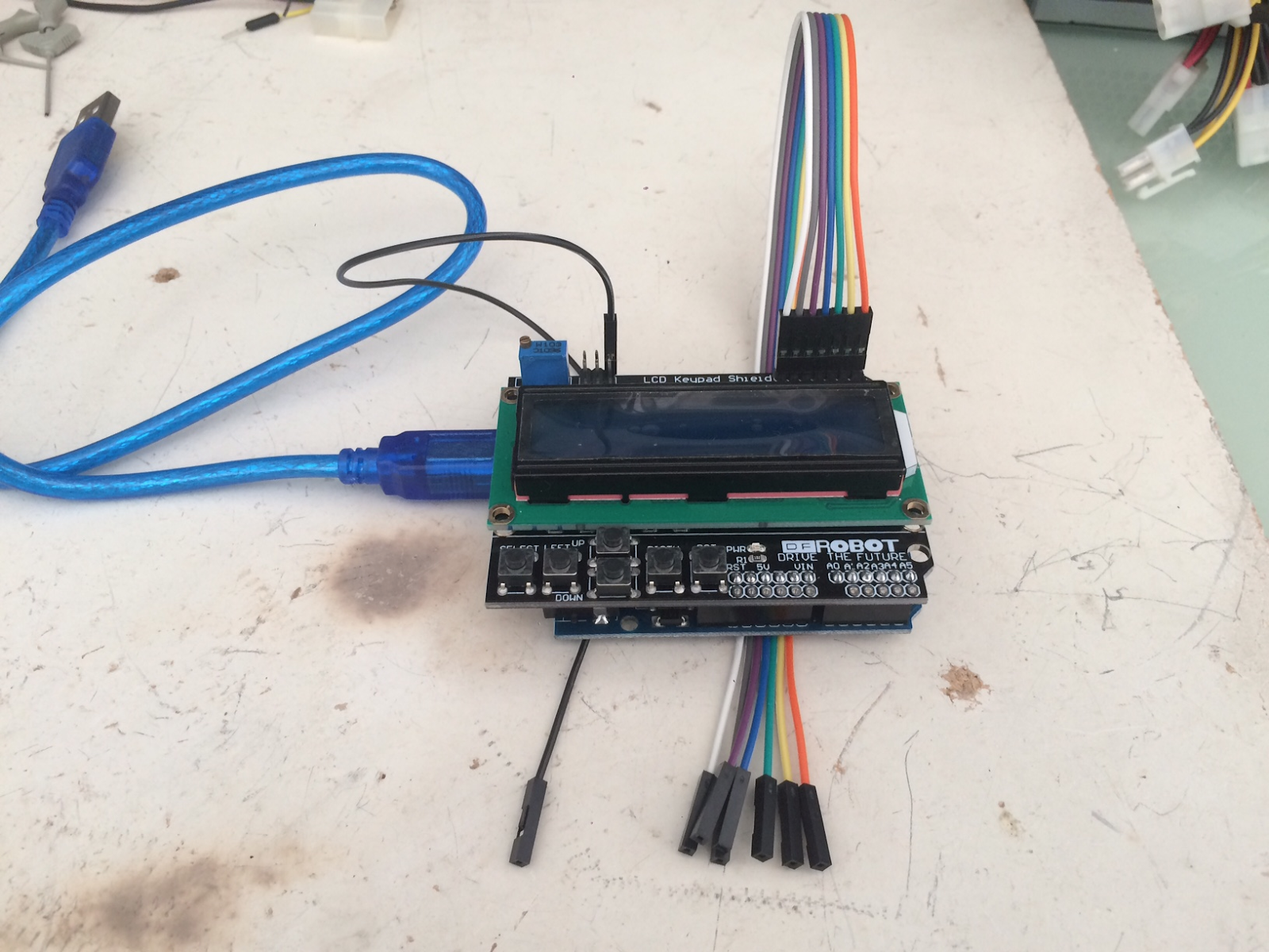
Assembling and preparing your Arduino programmer
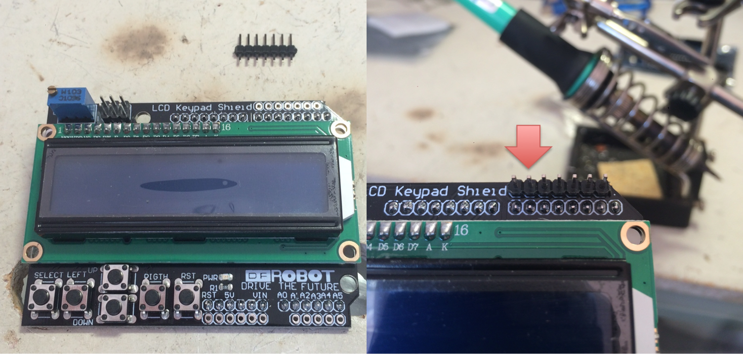
- Solder the 7 pin strip to the top right most socket of the LCD Keypad Shield
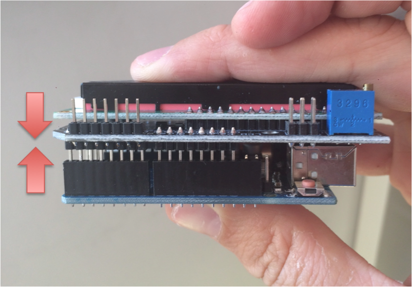
- Assemble the Arduino Uno and LCD Keypad Shield together
- Download and install software for your OS from https://www.arduino.cc/en/Main/Software
- Connect your arduino to your PC via USB
- Open the ArcadeHacker_CPS2.ino file in the Arduino environment.
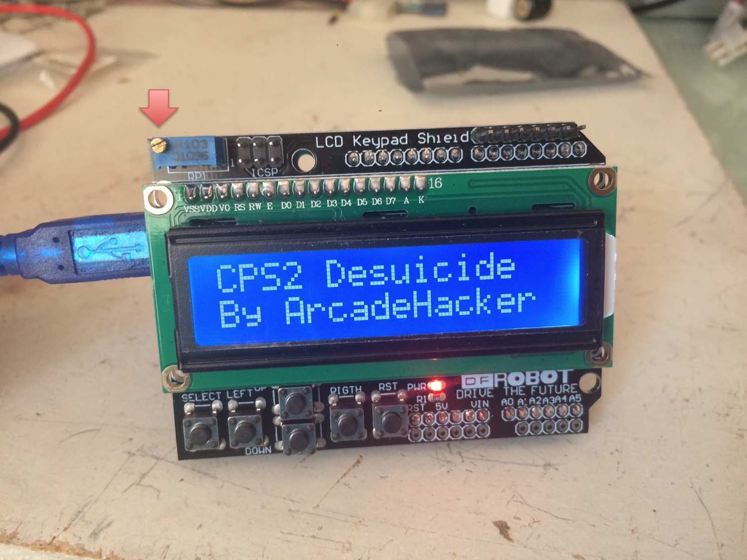
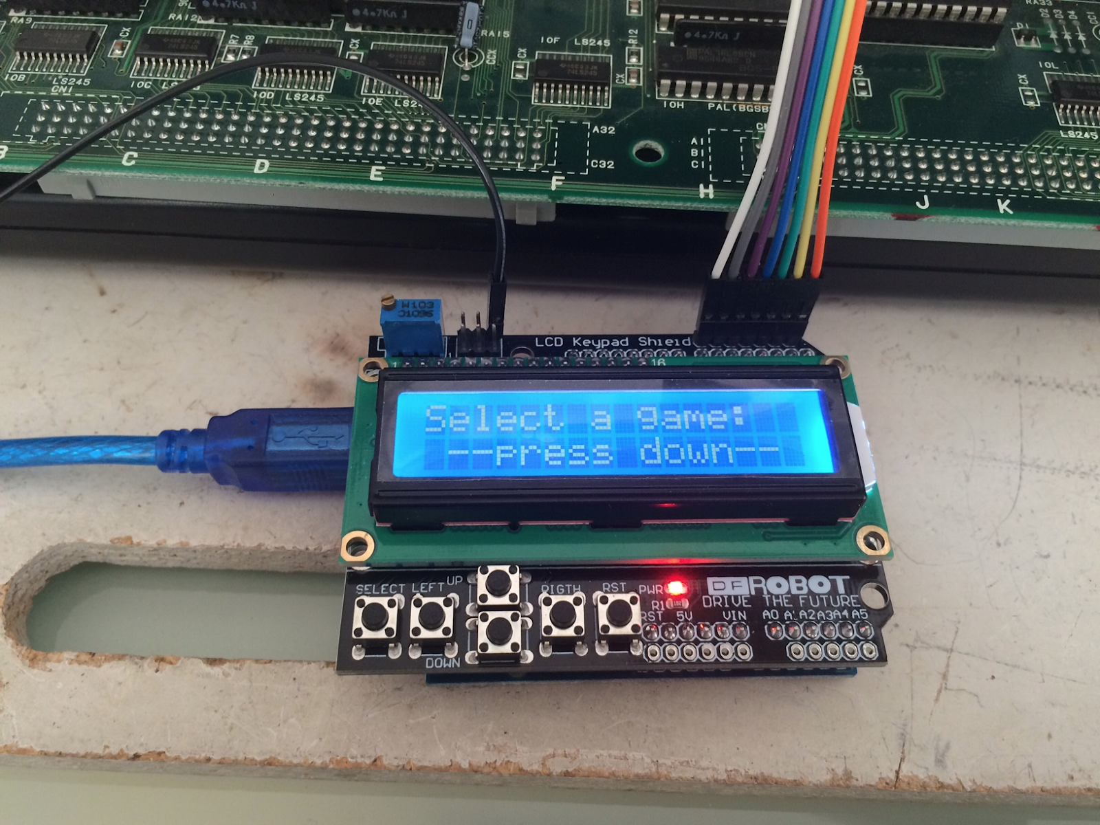
- Compile and Upload the sketch to the Arduino, next boot sequence should display what's shown below. If you can't see anything you may want to double check the screen contrast setting.
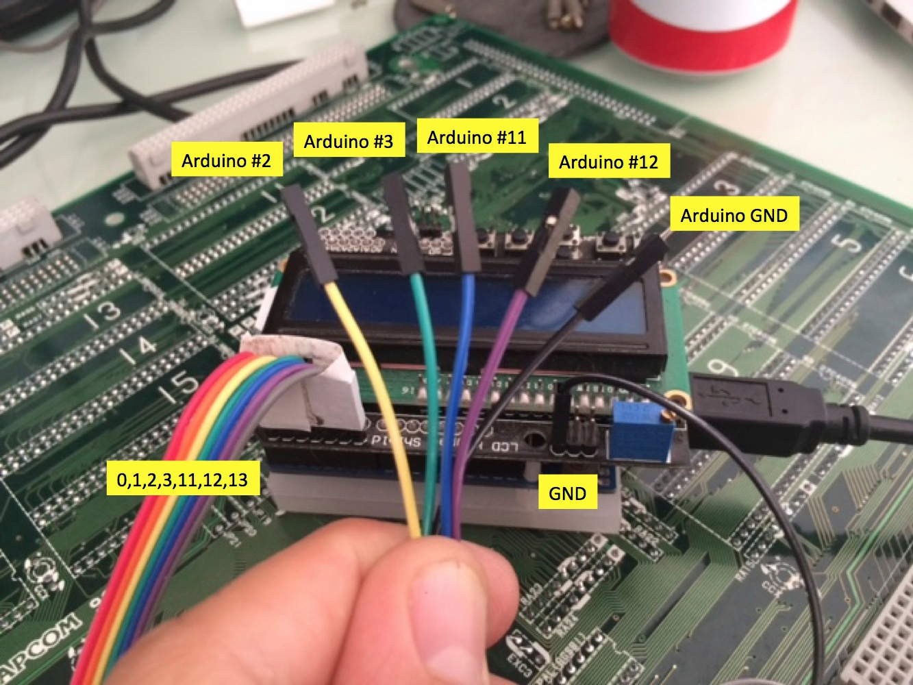
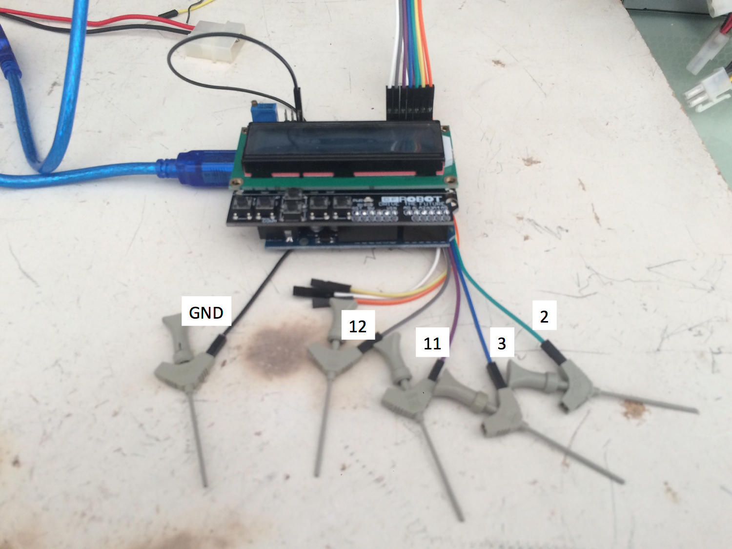
- Locate digital pins 2, 3, 11, 12 (top right) and GND (top left icsp connector) on your LCD Keypad Shield. Label them if possible.
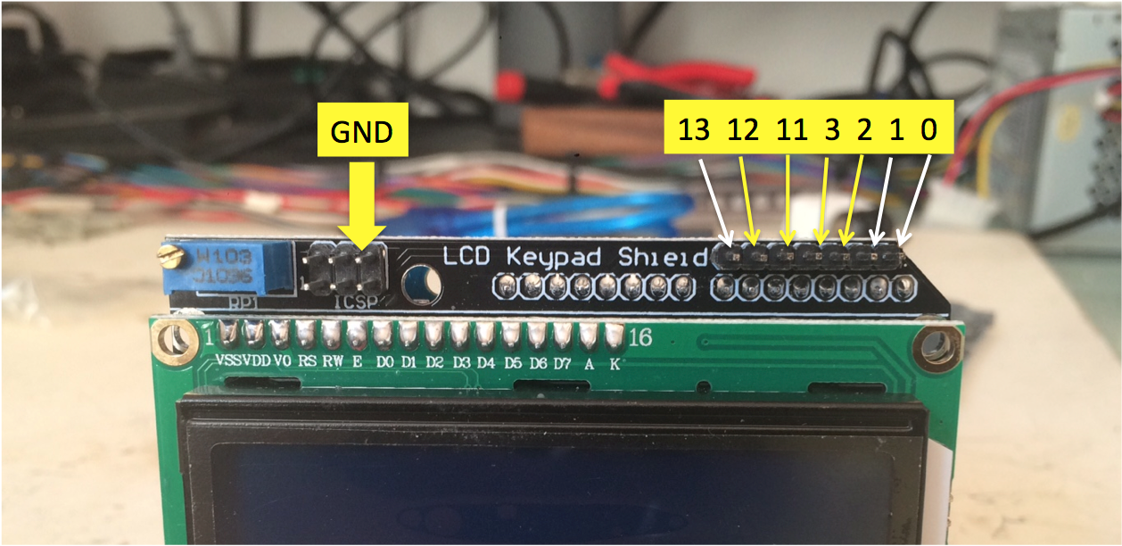
- Connect the dupont cables to the pinout as shown above. Label them if possible.
Assembling the CPS2 target power cable
Attach two female dupont ends to the female molex power plug.

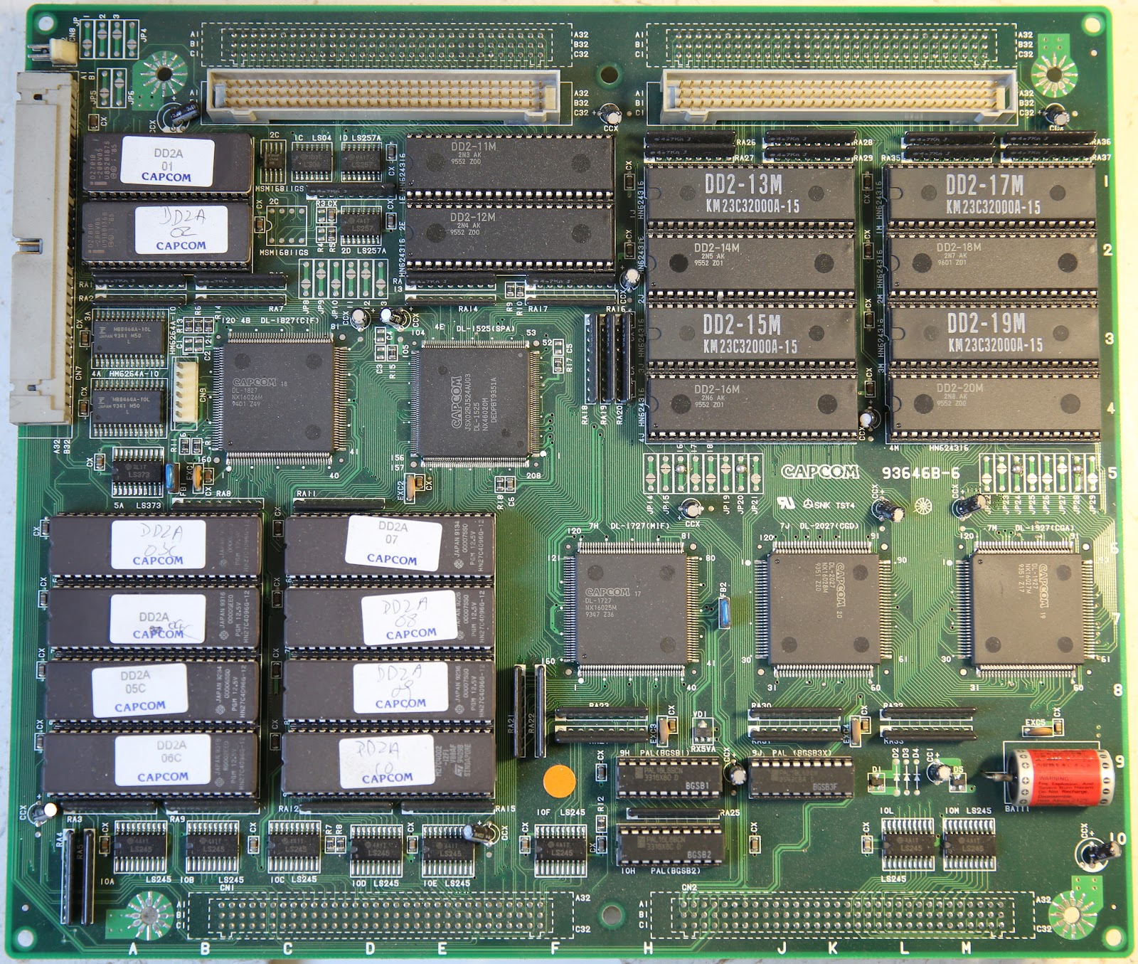
Identifying your CPS2 B board type
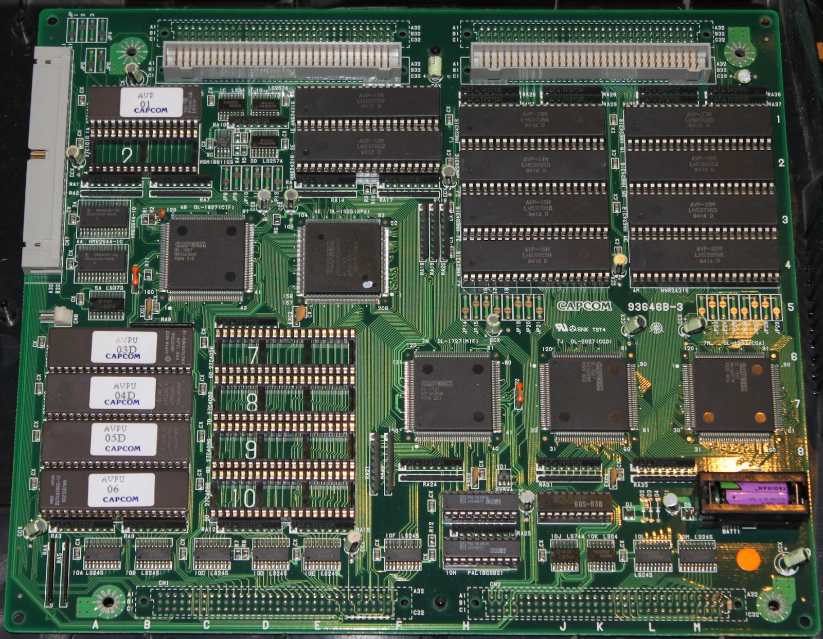
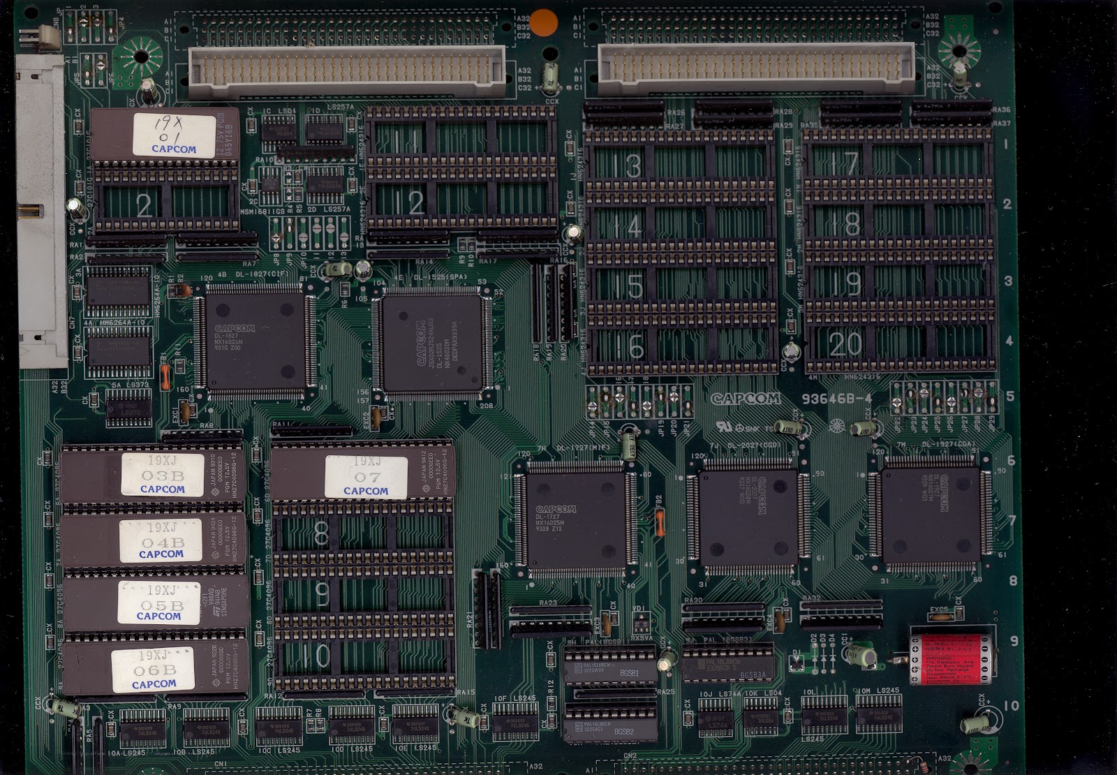
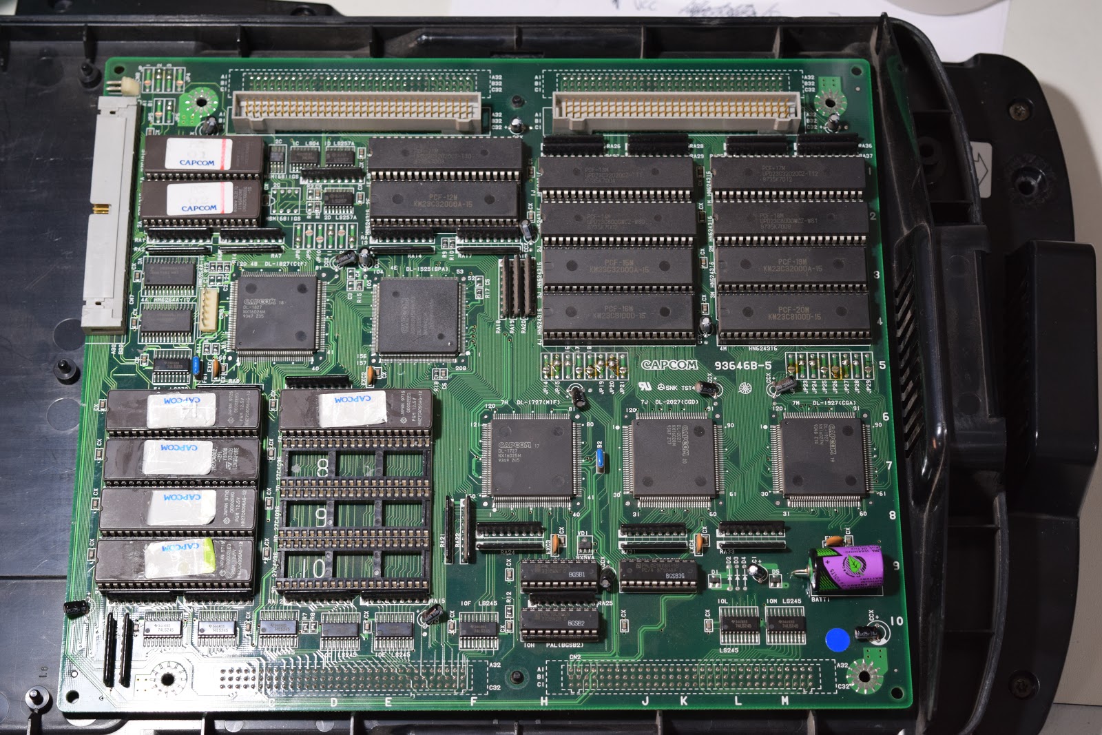
There are several revisions of PCB. These are the relevant ones:
93646B-3:
93646B-4:
93646B-5:
93646B-6 and 93646B-7:
97691A-3 and 97691A-4 (Black case, single board):

Pinout for board revisions 93646B-3 and 93646B-4
CN2 interface pins:
DATA Arduino #2 → CN2 A32
SETUP1 Arduino #3 → CN2 A30
CLOCK Arduino #11 → CN2 A31
SETUP2 Arduino #12 → CN2 A29
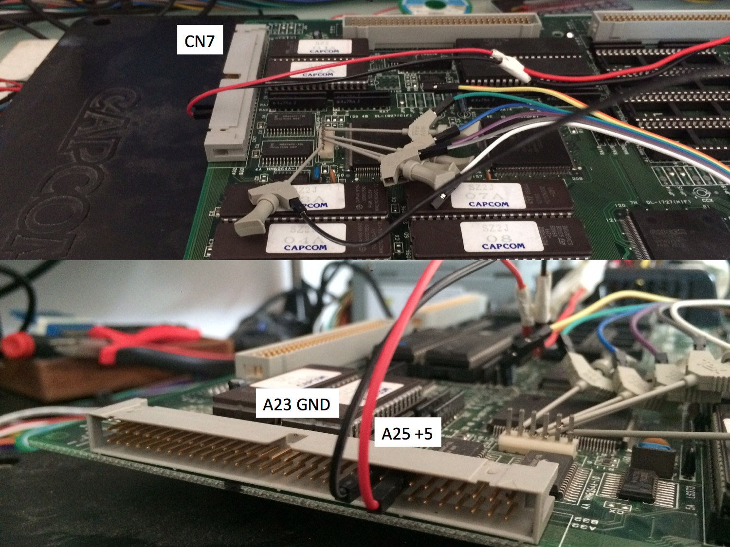
CN7 power pins:
+5V Power supply → CN7 A25
GND Power supply & Arduino GND → CN7 A23
GND Power supply & Arduino GND → CN7 B23
Pinout for board revisions 93646B-5
CN9 interface pins:
DATA Arduino #2 → CN9 #2
SETUP1 Arduino #3 → CN9 #3
CLOCK Arduino #11 → CN9 #4
SETUP2 Arduino #12 → CN9 #5
CN7 power pins:
+5V Power supply → CN7 A25
GND Power supply & Arduino GND → CN7 A23
GND Power supply & Arduino GND → CN7 B23
Pinout for board revision 93646B-6, 93646B-7 and 97691A-3
CN9 pins:
+5V ---------------- → CN9 #1
DATA Arduino # 2 → CN9 #2
SETUP1 Arduino # 3 → CN9 #3
CLOCK Arduino # 11 → CN9 #4
SETUP2 Arduino # 12 → CN9 #5
GND Arduino GND → CN9 #6
Preparing your CPS2 B board
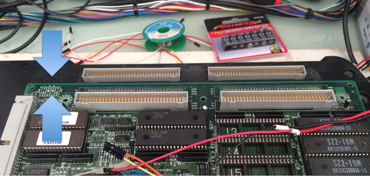
- Open the CPS2 B Board plastic case using the Torx Security T20 screwdriver head (the photo below does not apply to revision 97961A-3 "all in one black")

- Identify your PCB revision and check the battery voltage

- If needed replace the battery with a fresh spare, fit a battery holder when possible

Desuiciding revisions 93646B-3 and 93646B-4
- Connect your hooking cables to the corresponding outputs of the arduino programmer (2, 3, 11, 12 & GND)
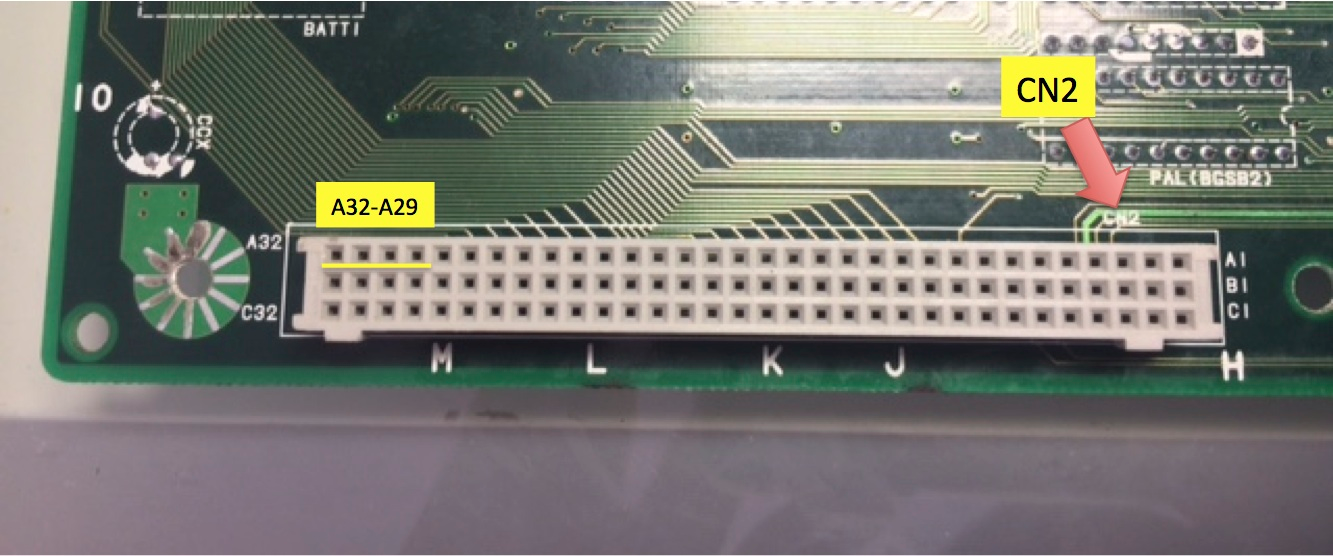
- Connect all pins to CN2 following the order described below.
DATA Arduino # 2 → CN2 A32
SETUP1 Arduino # 3 → CN2 A30
CLOCK Arduino # 11 → CN2 A31
SETUP2 Arduino # 12 → CN2 A29
GROUND Arduino # GND → CN2 C32

- Connect power cables to CN7 A23 & B23 (GND) and A25 (+5)
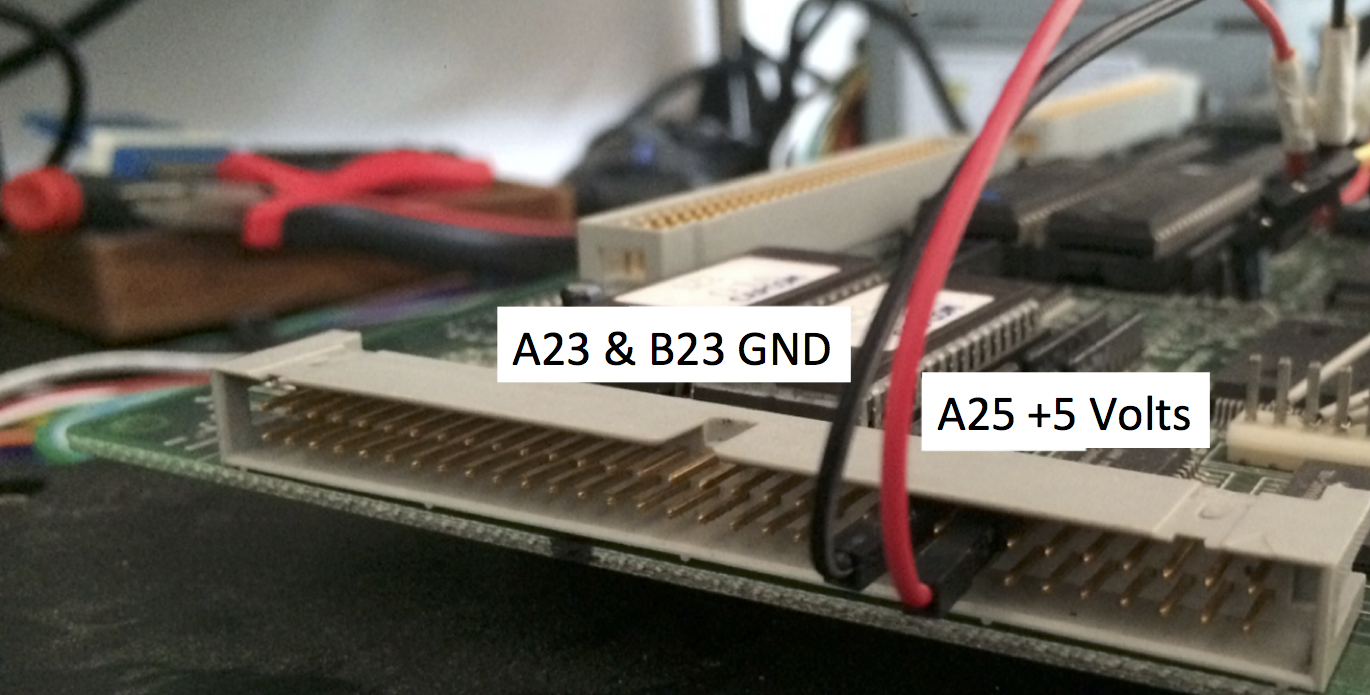
- Connect the molex connector to the power supply (power supply off!)

- Make sure the CPS2 A board and B board are disconnected from each other
- Turn on the power supply connected to your CPS2 B board, then power up your Arduino programmer (plug the USB cable to a USB power source, eg: your computer)
- Follow the on-screen instructions and program the game configuration you wish to upload. Use the up/down/right/left buttons to advance through the game options.
- Once programmed, disconnect power to the Arduino programmer followed by switching off the main power supply to your CPS2 B board
- Disconnect all arduino and power supply wires connected to the PCB
- Assemble the CPS2 A and B boards together and test for results. If unsuccessful take your time to review your setup before attempting a new keyload.
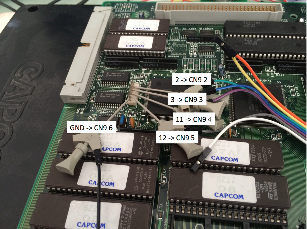
Desuiciding revisions 93646B-5, 93646B-6, 93646B-7, 97691A-3, 97691A-4
- Connect the ic clips to the corresponding outputs of the arduino programmer (2, 3, 11, 12 & GND)
- Connect all grabbers to CN9 following this order. You can also use a JST NH 6pin connector, pins are part number SHF-001T-0.8BS or SHF-002T-0.8BS depending on your wire gauge.
DATA Arduino # 2 → CN9 #2
SETUP1 Arduino # 3 → CN9 #3
CLOCK Arduino # 11 → CN9 #4
SETUP2 Arduino # 12 → CN9 #5
GND Arduino GND → CN9 #6
- [Revisions 93646B-6, 93646B-7, 97691A-3 only] Attach the power cable as shown below. GND connects to the existing arduino grabber.
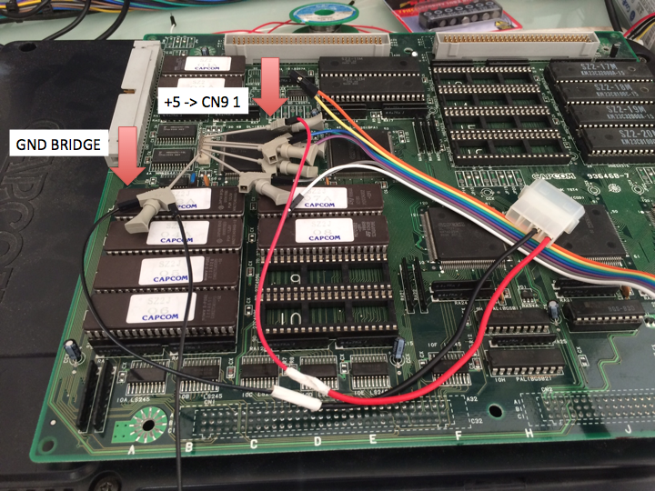
- [Revision 93646B-5 only] Connect power cables to CN7 A23, B23 (GND) and A25 (+5)
- Connect the molex connector to the power supply (power supply off!)
- Make sure the CPS2 A board and B board are disconnected from each other
- Turn on the power supply connected to your CPS2 B board, then power up your Arduino programmer (plug the USB cable to a USB power source, eg: your computer)
- Follow the on-screen instructions and program the game configuration you wish to upload. Use the up/down/right/left buttons to advance through the game options.
- Once programmed, disconnect power to the Arduino programmer followed by switching off the main power supply
- Disconnect all arduino and power supply wires connected to the PCB
- Assemble the CPS2 A and B boards together and test for results. If unsuccessful take your time to review your setup before attempting a new keyload.
Hands-on video tutorial by Artemio
https://www.youtube.com/watch?v=ulIi9B74HMs
Thanks for making this happen Ed
ReplyDeleteAwesome work guys! Thanks for all the effort and time you put to make this happen :)
ReplyDeleteAwesome work. You rock!
ReplyDeleteNow... On to CPS3?
ReplyDeleteAmazing stuff and awesome work to everyone involved! Thanks for the incredibly detailed write up too!
ReplyDeleteThanks for this. I'd screw it up myself but my cousin will get it done. Fantastic work.
ReplyDeleteThis is awesome! Thank you very much for sharing this with everybody. I am a big fan of the D&D games, now my Tower of Doom is safe if someday the battery is fully drained. From now on, do you have a new objective in mind?
ReplyDeleteThis is fantastic! Thnx for sharing! Sharing is caring and that is the true arcade spirit IMHO };-P
ReplyDelete<3 Elgen };-P
(ElgensRepairs)
Thank you very much for your awesome work! This is what arcade gaming should be about, preserving it on all levels!
ReplyDeleteIt begins with preserving the ROMs themself, goes over to sharing findings and finally keeping all the hardware alive as close to the original state as you can get.
Arcade games are no mass ware like Super Nintendos or Playstations, so people need to see how important this work realy is!!
Thank you again!!
Awesome!!!!
ReplyDeleteCan we program different games to different motherboards?
ReplyDeleteExample... xmen vs street fighter ... change to Super Street Fighter 2 turbo?
Are you planning to publish the details of how to go from the keys in the MAME source to the keys in the Arduino code? (e.g. if a game with a different encryption key is cracked open in the future?)
ReplyDeleteHe is preparing an post with the technicalities. I am very anxiously waiting for it myself.
DeleteAs for adding new keys, the code is very easy to read and understand. Adding new keys should not be an issue, at all.
He should keep those details to himself and not give away his work to the likes of the lazy and incompetent Mame devs, whom for years have practiced bad coding procedures like depending on global_alloc_clear, which bit them in the ass with Mame 176 with the ui menu appearing off the screen http://mametesters.org/view.php?id=6335. Funny I was the first to actually complain about it on the mameworld forums long before any lazy official Mametester noticed it.
DeleteLike I said, he should keep his secrets to himself and let the Mame devs figure it out on their own, or at least charge them a fee for the info.
@Anonymous: Some of the guys with whom we collaborate *are* also MAME devs. We're on good terms, and intend to keep it that way.
DeleteMuchas gracias por este arduo trabajo para preservar la historia de los videojuegos.
ReplyDeleteThis is truly amazing
ReplyDeleteGreat work!
Eduardo.....It's just fantastic ^^
ReplyDeleteThanks, a dream come true :)
Cps1 and now Cps2 you're a good killer ^^
Respect man :) i'm your fan lol ;-)
wow! i can fix my all battery dead ROM, thank you very much! :)
ReplyDeleteThis is some absolutely INCREDIBLE work and THANK YOU for doing this! :)
ReplyDeleteAs an owner of a couple of grey Asia region CPS2 boards, I will now be able to revive my dead games.
I am especially fascinated as to how this works inside the actual chips.
Do you plan on putting together another technical presentation like the one with the CPS1 desuicide project?
I did some guesswork on how I thought the CPS2 logic worked in one of your previous blog entries and am eager to see how wrong I was. :) I am eager to learn about the differences in the engineering techniques were between CPS1 and CPS2 (and CPS3's SH2 custom cpu?). I was betting it was the same guy(s) @ capcom's product technology division!
You sir, are an inspiration and I thank you again for keeping my mind open and active.
Muchas gracias!
This works for CPS 1.5 / DASH - The Punisher?
ReplyDeleteAmazing work! Thank you for releasing this!
ReplyDeleteWow nice!
ReplyDeleteDoes it work with Black board CPS2? (I own a Hyper Street Fighter II)
Thanks :)
Yes, it works with black all-in-one CPS2 boards. :)
Deletethank you for this
ReplyDeleteSooo...your telling me this will make a cps2 board "rise from your grave"...(altered beast style)
ReplyDeleteHi Eduardo !
ReplyDeleteI'm a french arcade collector.
Your work is very impressive. So fast and efficient !
I follow your cps2 tutorial and bought a Genuino Uno.
Thanks to you, my Marvel vs Capcom single black work again now :-)
Ian Court said that's working for black all-in-one CPS2 boards.
I found Marvel vs Capcom in the list (mvscjsing), and I confirm that's working great !
But I don't found the 5 others titles in the list (Gigawing, Street fighter zero 3, Hyper street fighter 2, Mars Matrix and Dimahoo)
It's not working for these single black board for the moment, or we can use the same code as japanese B board ?
Moreover, I have a problem with ArcadeHacker-CPS1 and ArcadeHacker_Kabuki-Master.
When I want to verify/compile, it's not working, I have this message:
collect2.exe: error: ld returned 5 exit status
exit status 1
Error compiling for board Arduino/Genuino Uno.
Here's come a pic of this message:
http://hpics.li/871ff0e
Have you any idea for help me ?
Or I need another Arduino/Genuino like the MEGA version ?
Thanks for all ;-)
For your other all in one boards, just use the keys for the regular B-board type, selecting the appropriate region (Japanese for most, if not all black boards I believe). Please confirm if it works or not! :)
DeleteWe'll have to get back to you regarding your issues with Kabuki and CPS1.
I'll not confirm that's working with my others black board, because they still working and I change the battery few years ago.
DeleteI just have a dead MvC for test, so I can confirm with this game.
If someone have a dead black board game, I can try and leave a feedback as soon as possible...
Thanks in advance for the 2 others tuto (I have a dead block block in a box XD)
Hi Eduardo !
ReplyDeleteI'm a french arcade collector.
Your work is very impressive. So fast and efficient !
I follow your cps2 tutorial and bought a Genuino Uno.
Thanks to you, my Marvel vs Capcom single black work again now :-)
Ian Court said that's working for black all-in-one CPS2 boards.
I found Marvel vs Capcom in the list (mvscjsing), and I confirm that's working great !
But I don't found the 5 others titles in the list (Gigawing, Street fighter zero 3, Hyper street fighter 2, Mars Matrix and Dimahoo)
It's not working for these single black board for the moment, or we can use the same code as japanese B board ?
Moreover, I have a problem with ArcadeHacker-CPS1 and ArcadeHacker_Kabuki-Master.
When I want to verify/compile, it's not working, I have this message:
collect2.exe: error: ld returned 5 exit status
exit status 1
Error compiling for board Arduino/Genuino Uno.
Here's come a pic of this message:
http://hpics.li/871ff0e
Have you any idea for help me ?
Or I need another Arduino/Genuino like the MEGA version ?
Thanks for all ;-)
This is really amazing, thank you for this. I am putting the parts together currently, to resurrect my Street Fighter Alpha board which just suicided while changing the battery. Finding a good source for a JST NH 6 connector has been extremely challenging. Digging through my spare connectors drawer, I found the below connector which attaches perfectly to CN9 and CN7. It can probably be purchased at a local electronics store (like Fry's) or online easily.
ReplyDeletehttp://s56.photobucket.com/user/noaffinity/library/Good%20Connector%20for%20CPS-2%20Desuicide
Where is the best place to post results of my effort, once I get everything together and follow these instructions?
Thanks for sharing your tips, please keep the coming.
DeleteDisregard my post from late last night. I have re-checked my setup this morning, and followed the instructions implicitly, and now have a working SF Alpha board! Thank you so much for this amazing contribution! FYI, to others that will be doing this, be sure to strictly follow the instructions of powering the board first, then powering the arduino; and when done programming, de-energize the arduino first, then de-energize the board.
ReplyDeleteI have a 93646B-4 board I am looking to revive. It looks like the CN7 A25 and B25 +5V pins are connected. Can anyone verify this as well?
ReplyDeleteAmazing work! You guys really have your names set in stone for such an achievement in arcade preservation. One question though: is the key the same between different revisions of the same game?
ReplyDeleteHi there, in cps2 capcom used different keys for game regions.
DeleteThis comment has been removed by the author.
DeleteThanks for an answer. But my question was about different revisions of the same region release. Like Street Fighter Zero 2 revision 960430 and Street Fighter Zero 2 revision 960227.
ReplyDeleteIIRC same keys across revisions. Regards.
DeleteI just checked out your site. I like Arcade games and I'm still learning tricks of programming when it comes to hacking. Could you provide some info on hacking pinball flash games in IE, Firefox or Chrome?
ReplyDeleteAnother board de-phoenix'ed and returned to native suicide battery operation. This time, Street Fighter Zero 2 Alpha. Re-programmed the roms with SFZ2ALJ set from MAME, as well as SFZ2ALJ encryption key.
ReplyDeletehttps://youtu.be/jzlMikTSzGc
Good one!
DeleteHaving issues resurrecting a previously known working AVSPJ board, rev 93646B-3.
ReplyDeleteI noticed there is this inconsistency in the instructions:
Pinout for board revisions 93646B-3 and 93646B-4
CN2 interface pins:
DATAArduino #2→ CN2 A32
SETUP1Arduino #3→ CN2 A30
CLOCKArduino #11→ CN2 A31
SETUP2Arduino #12→ CN2 A29
CN7 power pins:
+5VPower supply → CN7 A25
GNDPower supply & Arduino GND → CN7 A23
GNDPower supply & Arduino GND → CN7 B23
Then further down:
Connect all pins to CN2 following the order described below.
DATAArduino # 2→ CN2 A32
SETUP1Arduino # 3→ CN2 A30
CLOCKArduino # 11→ CN2 A31
SETUP2Arduino # 12→ CN2 A29
GROUNDArduino # GND → CN2 C32
Connect power cables to CN7 A23 & B23 (GND) and A25 (+5)
Tried both ways, but neither seems to work for me.
Another board resurrected, for a fellow collector. Alien vs. Predator USA blue board. :)
ReplyDeleteSorry, but orange 93646B-4 with MVC Brazil is not working.
ReplyDelete93646B-7 with MVC Hispanic is ok.
Thanks for your work guys.
Hi Raph, happy to go over with you on the orange box issue, let me know if you would like to do so.
DeleteOlá, Eduardo, how are you?
DeleteMr. Artermio tried help me in his youtube channel (https://www.youtube.com/watch?v=YSiPd8z4fes&lc=z12ojrdbwoafulwf2220upaoaky1zh2y104) but i always the same results. I do the process but the -4 board is still dead.
Others -6 and -7 are all good, only the -4 orange is a problem.
I remade the cables and nothing.
I'll wait till a new method comes.
Thanks man.
Never experimented with the orange type boards. If you are willing to send it over to me I would definitely put time in to understand why it doesnt work. Let me know if you like the idea. Regards.
DeleteHey man, if you live in Brazil, will be easy to send, but overseas is alot expensive :(
DeleteDo you know Leonard Oliveira by any chance? I believe he is local and perhaps able to look into this?
DeleteWe did talk a little at Assemblegames forum but it's offline at moment and i don't have his contact :(
DeleteLeo just commented further below, please follow his conversation.
DeleteDe-suicided a MVC blue US board (93646B-4) for a fellow collector.
ReplyDeleteHi there! I have desuicided 93646B-4 boards of any kind including one gray (asia board) and never had any issue besides the first time (the order of the wires is different than the order on CN9 boards).
ReplyDeleteOnce I fixed the wiring it started working every time. Also, I use exactly that board version with CPS2 multi and a self built Arduino CPS2 programmer:
https://drive.google.com/open?id=0B4uDzZi6unHVOC1qWnc1eEt4cFE
https://drive.google.com/open?id=0B4uDzZi6unHVdmtZZFVUSU9oX3M
With that I can flash encrypted sets into that CPS2 multi and boot them after programming the keys using the Arduino device.
Fala Leo, obrigado lá pelo MVS, deu certo regravando a imagem do sfix em uma eprom, não consegui te avisar porque o fórum caiu.
DeleteEu coloco na ordem proposta aqui e não dá certo de forma alguma, a placa continua morta.
----------------
Personal talk in portuguese, now the question in english:
My board is still dead ever with the wiring order here propose, all my -4 are still dead.
My multimeter mark around 4.6 or 4.8 V on the board, that's a problem? I'm using a generic ATC PSU.
Can you send me some video or pics that can help me a little?
Thanks man.
Do you have a direct contact? E-mail maybe?
DeleteHey
ReplyDeleteI'm having a problem. I took a board that was desucuided and reburned the roms. I can not get your device to work at all on that board. What am I missing
Still can't get it to work
ReplyDeleteStill can't get it to work
ReplyDeleteGot my Vampire Savior (Jap) back from the dead. Great work guys!
ReplyDelete(2) X-men vs. SF, both US 961023 code. One board is rev -3, one is rev -7.
ReplyDeleteFor those having trouble with -3 and -4 boards, I've found the following is the correct pinout:
Power supply +5V -> CN7 A25 (top row of CN7)
Power supply ground -> CN7 B23 (bottom row of CN7)
Note your ground for this connection has to come from your power supply, NOT the arduino.
Also, power the game board first, then power the arduino. When done re-programming, remove power from the arduino then the game board. If none of this works, start looking at your board for any signs of damage or other potential causes for problems. On the rev -3 x-men board referenced above, I found a diode and its traces completely scraped off the board, which had to be repaired in order for the board to be re-programmable.
Hi all,
ReplyDeleteI have an AVPU Board where the battery popped out, it cold boots to a light green screen, when I power off then back on it's a black screen.
I tried the 93646B-4 method over a dozen times. I switched the pin 25 (5v) from A to B, vice versa. Would this kill the board? I am replacing the battery holder with a battery with leads next week, and will try this again.
Is there any way to test or tell if a B board is dead?
Also I see Chris G's clarrification post. Question - Is row A closest to the board or the row away from the board?
Thank you.
Chris G and I have communicated outside of this site. Thank you Chris for pointing out where the A Row is for the +5V connection (top row - row furthest away from the board).
DeleteI have done the following in preparation for next week:
- Unsoldered the battery holder
- Cleaned all the damn flux that was used
- Ordered new batteries with leads
- Ordered a new Arduino to eliminate that option
- Will go over the board in it's current state to make sure there is nothing broken on it.
Please Note: This board looks brand new, as I mentioned to Chris you have to see it to believe it.
Also this board is a complete original, zero aftermarket with the exception of the battery holder that was soldered to it. Chips are all genuine Capcom.
Will keep you all posted as I go down the rabbit's hole, hopefully it will be a success.
Best regards,
Javier
I've now fallen victim to the CN2, rev -4 woes. I wiped the encryption key on my SSF2T board, to do some testing with decrypted roms. I cannot get it to reprogram. Through days of troubleshooting and attempting it on other known good boards, one of which was previously desuicided, I now have (2) rev -4 boards that won't program and (1) rev -3 board that won't program. Interestingly, I also killed a rev -7 w/ CN9 board, but that one reprogrammed and is back to life. Eduardo - I sent you a PM via Arcade Otaku forums. Hoping for some help here. And ^ Anonymous, CN7 A23 and B23 are both grounds, CN7 A25 and B25 are both +5V. You can check at teh appropriate legs of any of the program ROMs for good voltage once you have your power supply connected to CN7.
ReplyDeleteUpdate - after a week of pulling my hair out over this problem. I have resurrected all 3 boards. Turns out it was the power supply that I was using to power the Arduino. It was rated 7.5V and outputting 12V. Arduino spec is an acceptable range of 6V - 20V, and recommended range of 7V - 12V. Should've been within spec... On a hunch I started testing different power supplies this morning. Some should've been with spec and produced odd results with the Arduino. I finally ended up on a 5V 4A power supply, metered at 5.17V output when powered. Not within spec for the Arduino, but this is the one that ended up working to resurrect all 3 boards. So, if you're having problems programming boards that require the Arduino data to be pushed through CN2, try powering the Arduino with a 5V power supply.
DeleteAny chance you will you be tackling SEGA/Hitachi FD1094 in the future?
ReplyDeleteI was looking through the list after download and couldnt find Three Wonders in there. I was wondering if this would be available in another updated list or not as this is one board Im trying to revive now. If a donation is required I dont mind that either, I would just like to get my board back up and running. Please let me know and thank you for your hard work on this.
ReplyDeleteLuke
I was looking through the list after download and couldnt find Three Wonders in there. I was wondering if this would be available in another updated list or not as this is one board Im trying to revive now. If a donation is required I dont mind that either, I would just like to get my board back up and running. Please let me know and thank you for your hard work on this.
ReplyDeleteLuke
Hi Luke, Three Wonders is a CPS1 game not CPS2 , check this post: http://arcadehacker.blogspot.com.es/2015/09/project-update.html
DeleteThank you for the quick reply Eduardo. For some reason I thought it was all in the same zip file and I was missing something. Got the other files and thank you so much for making this. If you have a donation page let me know.
ReplyDeleteReally great to have this as a resource .
Hello
ReplyDeleteFirst of thank you so much for this,
I have tried everything with my Xmen vs street fighter EU version
sadly it didnt work at all changed battery and tried Phoenix it and then programming it with "xmvsf"
sadly nothing :( not sure what i did wrong
First, many thanks for the tool, I de-suicided 3 boards here already!
ReplyDeleteSecond, a question: I got a Street Fighter Alpha 2 (960306 USA) (dumped all the progam roms to confirm it's exactly this ROMset), and it didn't work, even after 3 or 4 attempts.
I've checked the source code and the entry for this ROMset (sfa2ur1) is missing. So does it mean we need to wait you guys to add it to the program, right?
I re-checked MAME source code, and confirmed it uses sfa2 keys. How I have done it:
DeleteNote: mine is a rev 4 board
- Connected pins to CN2;
- Connected 5v to A25 and GND (both from PSU) to A23;
- Zeroed keys with Phoenix option;
- Inserted CPS2 suicide Test and it booted, so it was properly zeroed, I presume;
- Wrote sfa2u keys;
- CPS2 suicide test doesn't boot anymore, so it was written on the board, I presume;
- Put original 03 game ROM back into PCB slot 03;
- Still not booting (solid purple screen in my case).
What can I be doing wrong? I checked pins A25 and B25 from CN7 with multimeter and both have continuity, but it doesn't happen with pins A23 and B23. (A row = lower row and B row = upper row)
Also, if I connect GND to B23 the cable overheated, So it was something wrong too, I presume.
You can use sfa2u as it shares the same encryption keys with sfa2u1. This set was tested by us and is market as working, I recommend that you attempt a different board revival in order to discard that the hardware is at fault.
DeleteMake sure you have a good T20 Security Torx screwdriver when you open the CPS2 B Board plastic case so you don't mess up the head of the Torx screws. Cheap Torx screwdrivers can have soft tips and booger up the screws. I found some nice ones at https://besttoolz.com/torx-screwdriver-buyers-guide/ that worked well.
ReplyDeleteHello. I am currently stuck at desuiciding my Rev 7 MARVEL vs CAPCOM board and my Rev 7 MARVEL SUPER HEROES board. I have all the necessary equipment needed but have been trying to find a video tutorial or blog on how to exactly compile and upload the sketch to the Arduino Uno. Any and All help will be greatly appreciated. Thank you
ReplyDeleteQuestion when you solder in the 7 pins do they connect via the traces on the board to those corresponding pins or do I need to make jumper? Thank you sir! This is great work
ReplyDeleteI'm having some issue with reprogramming the keys.
ReplyDeleteI bought a Japanese Vampire Hunter: Darkstalkers Revenge. -4 board.
Battery was dead, no leakage. Putting in the suicide tester shows all chips as good.
Programmed the key using the Arduino. Connected with 5v power and GND to CN7. Arduino pins 2, 3, 11, 12, GND to CN2.
After programming, suicide tester no longer works (as expected). Placed the original 03 chip back in, but the game won't boot. If I program Phoenix, suicide tester works again.
So, I think my connections are good?
Any ideas or suggestions on what I could do? As far as I can tell, everything in this board is stock.
hi again..waiting a street fighter 2 zero (*death)..but the software from arduino have only sfz2a?its same key ?or how is the correct name ?
ReplyDeletetanks allot for your time
What's the Mame romset name?
DeleteThis comment has been removed by the author.
DeleteThis comment has been removed by the author.
ReplyDeleteWhat's the color of the case? blue/grey/green...etc
DeleteThis comment has been removed by the author.
ReplyDeleteoh thanks allot for your time !!keep hard work
ReplyDeleteI want to thank you so much for posting this process, as it's helped me resurrect a USA Tower of Doom from a dead battery with no issues along the way. Such a simple process for us to follow from the hard work you and others put into making this happen.
ReplyDeleteHere's my experience:
https://twitter.com/codeX_ATA/status/1081732420636950532
Hi Eduardo thanks for making this Happen i am confused about the ground situation so im trying to resurrect a street fighter alpha 3 usa board revision 93646B-3 and i have the following questions
ReplyDelete1. do i have to connect the ground coming from the atx power supply molex to the one coming from the arduino and then from there go to the c2 ground connector and two c7 ground connectors?
2. in the picture it looks like you only have on power 5v connector going to c7 a25 and a single ground to a23 is this correct?
3. the confusion arose from the fact you mention the following
GND Power supply & Arduino GND → CN7 A23
GND Power supply & Arduino GND → CN7 B23
so does that mean i have to connect to those two point or just a23?
any help is appreciated thank you
Thanks again Eduardo for your job !
ReplyDeleteIf somes are interested, I just upload hex files for PIC12F625 for a definitive installation.
One per game :
https://github.com/ajefr/CPS2_Modchip
Have fun !
Hello,
DeleteI am looking for the ssf2r1 key, it seems no to be present in this code. Please can you share it.
Best Regards.
here's a weird one. SSFU, original seals, roms never touched. Verify as SSFJ...and does not work with either set of keys.
ReplyDeleteBlue case too.
Hola trato de revivir mi cps2 ssf2xjr , meto la llave y nada, la duda es en A23 Y B23 dice tierra y arduino, tengo la duda, no solo va la tierra de la fuente a estas terminales? o de la tierra del arduino conecto a A32 y a su vez me conecto a una tierra de la fuente y la pongo en A23 Y B23 CN7??
ReplyDeleteI tried the SPF2T key with my Puzzle Fighter 2 blue board, but it doesn't seem to work. I saw that for the InfiniKey device, they have an SPF2TU listed. I'm assuming that is for the USA version. Is there any way to update the ino file to contain the encryption keys for this version?
ReplyDeleteHello,
ReplyDeleteThank you so much for this amazing job.
Please can you give me the key value for ssf2r1 it doesn't appear in the .ico list.
Hello,
ReplyDeleteAnyone can help me with sharing the SSF2R1 key.
I can't find it.
Best Regards.
Dear community, I am trying to resurrect my old CPS2 Jap Vampire Hunter Darkstalkers Revenge. I used it in the past for a conversion I never completed but I missconfigured the jumper configurations in the process. If someone has this game (jap version) , could you please provide the jumper configuration from JP14 to JP29 (solderings)? Currently I have SOSOSOSO SOSOSOSO and with this config I am unable to recover the key with this method created by arcade hacker. Thanks in advance!
ReplyDeletePlease i am trying to desuicide a rev 4 board, no success. These questions are not answered yet, and it think i have the same problem/miscabling and confusion, please Eduardo, answer:
ReplyDelete"Hi Eduardo thanks for making this Happen i am confused about the ground situation so im trying to resurrect a street fighter alpha 3 usa board revision 93646B-3 and i have the following questions
1. do i have to connect the ground coming from the atx power supply molex to the one coming from the arduino and then from there go to the c2 ground connector and two c7 ground connectors?
2. in the picture it looks like you only have on power 5v connector going to c7 a25 and a single ground to a23 is this correct?
3. the confusion arose from the fact you mention the following
GND Power supply & Arduino GND → CN7 A23
GND Power supply & Arduino GND → CN7 B23
so does that mean i have to connect to those two point or just a23?
any help is appreciated thank you
Rev 7 Board looses key after some hours, fresh battery installed! any ideas?
ReplyDeleteSounds like the battery is unable to power the circuit while at rest. Check your battery voltage, if correct then check the voltage reaching the power rail while the pcb is not being powered. If correct, leave the pcb to rest for a while and check again. Most likely the capacitor that holds the power reserve is not being feed while the pcb is at rest. IIRC there's a diode or transistor nearby in charge of switching power from one source to another (vcc vs vbatt)
DeleteThanks! Caps seems ok, Diode D1 and D5 holding around 0,6 V dont know if this is correct.
Delete